
Thermal Analysis for EPTA Device
- Alberto Ricciulli

- 28 set 2020
- Tempo di lettura: 3 min
Aggiornamento: 14 ott 2020
FEA is utilized to design an Epidural Thermal Posterior Annuloplasty Device
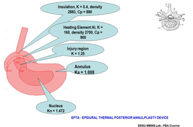
Figure 1. Material properties for EPTA
For this FEA project it is requested to design an EPTA device with only the information given in Figure 1.The temperature of the heating device was given in the range of 50 to 100°C.
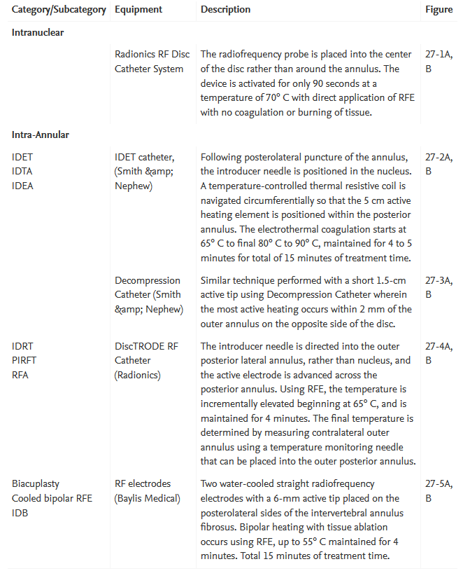
Standard methods require that the treated zone is heated at a temperature above 60°C for 4 to 5 minutes in order for the treatment to be effective. Although, too high a temperature may have detrimental effects leaving a narrow range of possible treatment temperatures [5]. Standard methods are listed in Table 1.
Table 1. Different EPTA procedures
Derby et Al. In Table 27-1, from chapter 27 of Evidence-Based Management of Low Back Pain, 2012.
In accordance with methods listed in Table 1, an applied temperature of 69.5°C is chosen. One can see the temperature gradient in Figure 4 along the cut-line in Figure 2. In comparison, the temperature gradient in Figure 3 shows that a temperature of 65°C is insufficient to maintain a temperature of 60°C throughout the entire area. Additionally, Figure 5 and 6 show the temperature distribution at the end of the treatment simulation.
Newell at al. reported that the nucleus is composed of 90% water and that this percentage reduces with age [3]. As such, the Specific heat capacity at constant pressure (Cp) of the nucleus is approximated to the one of water.
In the annulus, the composition is made 70% of water and the rest of dry material [1,2,3]. Hence, the Cp assigned were the same but an incremented density was selected [1]. The Cp of the inured reason does not vary. However, here the density is chosen to be the average of the two materials. Material properties are summarized in table 2
Table 2. Material Properties

A time dependent analysis is done using COMSOL Multiphysics. Given the parameters of standardized treatments, a simulation time of 5 minutes is performed with increment steps of 5 seconds. An initial body temperature of 36°C is assigned to the nucleus and the annulus as the normal body temperature. The convective heat flow coefficient (h) on the surroundings of the annulus has been chosen by T&A. The utilized method was to run the analysis without applying temperature from the device and controlling that the temperature distribution of the annulus
and the nucleus did not lower significantly from 36°C (figure 7). Here, it is assumed that not the whole spine is subject to the same flux as the exposure to the room must be less in the inside.
-An h=5 was determined.
The thermal conductivity (k) for better thermal management was also studied. Variation of k didn't affect significanlty the FEA results. To better account for optimal thermal management it is convenient to vary the heat transfer coefficient h and adjust the thermal conductivity accordingly (figure 8). A value of: h=0.5 W/(m2*K) and k=0.2 W/m*k were selected.

Figure 2. Cut-Line for temperature gradient evaluation


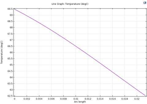
Figure 3 & 4. temperature gradient of the injured region at end of heat treatment. Left image has a starting T of 65°C; Right image has a starting T of 69.5°C.


Figure 5 & 6. Temperature distribution (left); Temperature distribution contours (right)

Figure 7. Determination of h for the annulus boundary conditions. a) h=5, b) h=29 c) h=50 d) h=750.

Figure 8. Insulator with h=20 @B.C.
References:
1) Intervertebral disc characterization by shear waveelastography: an in-vitro preliminary study Claudio Vergari et al.
2) https://www.toppr.com/bytes/specific-heat-capacity/
3) Biomechanics of the human intervertebral disc: A review of testing techniques and results N. Newel et al.
4) https://www.ncbi.nlm.nih.gov/pmc/articles/PMC5106353/
5) Derby et Al. In Table 27-1, from chapter 27 of Evidence-Based Management of Low Back Pain, 2012.
7) Dr. Kassegne, San Diego State University 2019, ME 610, Lecture 3 slides.
8) Finite Element Modeling For Stress Analysis - Robert D. Cook


Commenti