
System Integration and Configuration for Electrically Activated Reactive Synthesis Reaction Chamber
- Alberto Ricciulli

- 11 feb 2021
- Tempo di lettura: 3 min
Aggiornamento: 13 feb 2021
When I first joined the Advanced Material Processing Lab, I had to configure a Sintering Apparatus that was designed by a former researcher in the lab. The configuration of the chamber was essential for my thesis project as it was the means by which I had to create the material that successively I had to heat treat, test and analyze. It must be noted that the reaction chamber was dismantled and took apart prior to my starting date and by the time I was assigned to reconfigure it all the engineers who knew how to operate it had left the lab. Thus, this represented an extremely challenging project for me since I had very little circuitry and system configuration/integration experience.
Experiment Description.
The process of Reactive Synthesis (RS) occurs in the reactor chamber. In this experiment, RS is performed by placing a powder compact in between two copper rods that have been previously wired to a high rating power supply system. By doing so the sample closes the circuit and when a voltage is applied, current is able to flow from the power supply to the wires to then reach the copper rods, the sample and finally go back to the power supply. The reaction synthesis is achieved through heating of the sample at very high rates by the means of Joule heating. In RS, Electrically Activated Reactive Synthesis allows for several advantages including very high heating rates and uniform heating which diminishes the production of unwanted phases in the sintering process. Moreover, to avoid the formation of oxides the whole procedure is performed under vacuum. The synthesized material is Ni3Al with varying Carbon Nanotubes (CNT) content. The Nickel, CNT and Aluminum powders have been previously mixed according to the stoichiometric composition of the desired product. In addition, several mechanic treatments such as sonication and mechanical milling have been performed to facilitate the triggering of the reaction.
System & Subsystems overview.
The apparatus system is composed of:
· Vacuum Chamber
· Pumping Station
· Data Acquisition System
· Two Power Supplies connected in parallel
· LABVIEW software
The schematic of the Spark Plasma Sintering apparatus system is shown in figure 1.

Figure 1. Schematic of the Electrically Activated Reactive Synthesis system
Reaction Chamber.
The chamber is composed of a steel vessel which can be opened through two vacuum doors. The sample is sandwiched between two copper rods which connect the power supply to the sample. The steel parts are separated by the rods through the use of ceramic breaks and a Mica sheet so that the current flow is confined through the rod and the sample. The chamber is also equipped with a KF25 vacuum outlet to allow for the connection of the chamber to a vacuum pump. Finally, K type thermocouple feedthrough are also installed for temperature measurement. The Vacuum chamber and its components are shown in figure 2.

Figure 2. Reactive Chamber with list of features
Power Supplies, Data Acquisition System & LABVIEW.
A set of two TDK-Lambda Americas, 2U GENESYS Programmable DC Power Supplies capable of pumping four hundred (400) Ampere (at low voltage) each were set up in parallel in order to be able to have a current of eight hundred (800) Amperes flowing in the reaction system. The power supplies were configured to have a remote controlled slave power supply and a local controlled master power supply.

Figure 3 Illustration of the Parallel Connection where the load is to be considered the reaction chamber
A data Acquisition system was used to collect data from two thermocouples placed one in the chamber and one on the sample. Moreover, current and voltage output from the power supply were also recorded from the DAQ. The DAQ device utilized was the OMB-DAQ-2416 by Omega, Inc. Such DAQ provides both analog input and digital input/output but for the purpose of this project only analog inputs were utilized. The analog input channels are configured through the use of the software InstaCal. The software provides two possible configurations of the channels which are for Thermocouple and Voltage reading. The voltage configuration can be further set as either single ended or differential. In this setup the thermocouples were set as K-type and the voltage reading were set as differential by connecting the low reference channel of the analog input to the common of the power supplies.
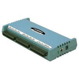
Figure 4. OMB-DAQ-2416 by Omega, Inc.
Finally, a LABVIEW code designed by a former researcher in the AMPL was recalibrated and utilized for the recording of the Temperature, Voltage and Current involved during the reaction.
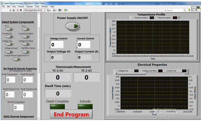
Figure 5. LabView front panel utilized in EARS experiments

Figure 6. Three different temperature and current profiles recorded while performing the reaction.
References.
[1] M. Chauhan, V. Bundy, P. Modi, and K. Morsi, “Electrically activated reactive synthesis (EARS) and electro-annealing of 3Ni–Al powder compacts,” J. Mater. Sci., vol. 53, no. 17, pp. 12512–12522, 2018.
[2] M. D. Chauhan, “Effect of Green Compact Density on 3Ni-Al and 3Ni-Al-Cnt Composite Synthesis Through Electro-Thermal Explosion,” 2018.
[3] Sonny L. Birtwistle, “INSTRUMENTATION OF ELECTRICALLY ACTIVATED PROCESSES,” SAN DIEGO STATE UNIVERSITY, 2017.


Commenti