
4-Point Bending Test Design of Experiment
- Alberto Ricciulli

- 24 mag 2021
- Tempo di lettura: 7 min
Introduction
This project involves the realization of a Four-Point Bending Test apparatus to perform experiments at room temperature, 300°C and 500°C. The material tested in these experiments is Ni3Al reinforced with the following quantities of Carbon Nanotubes (CNTs):
Ni3Al-0wt%CNTs Ni3Al-1wt%CNTs Ni3Al-3wt%CNTs Ni3Al-5wt%CNTs
With wt% indicating the weight percent of the reinforcement (Carbon Nanotubes).
Despite Ni3Al being an intermetallic and not a ceramic, testing procedures used for ceramic have been utilized as this material exhibits brittle failure. As such, the testing components were all designed to meet the ASTM standards C1161-18 and C1211-18 for flexural strength testing of ceramics at room temperature and elevated temperatures. Moreover, Ni3Al has reported to improve its mechanical properties at higher temperatures up until 1000°C due to its highly ordered microstructure. Thus, making the test of this material at higher temperature of high interest.
Thus far there is very limited literature information on flexural strength of Ni3Al alone and to the Author knowledge none at all on the Ni3Al-CNT composites systems making this project a cutting edge experiment in the field of material science.
Fundamentals of Bending test
Bending flexural tests are performed by loading a specimen under uniaxial bending stress. In a bending test, flexural strength, modulus of elasticity and deflection at fracture are determined. In this discussion a simple beam theory is assumed, conforming with ASTM standards C1161-18 and C1211-18 for flexural strength testing of ceramics. In simple beam theory, the bending moment is going to be highest at the cross section of maximum deflection to then linearly decrease to zero at the supporting pins [1-3].
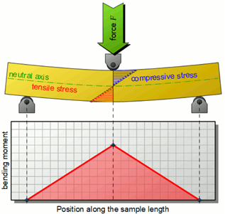
Figure 1 Bending Moment distribution in a beam during three-point bending [6]
During bending, the material will be subject to tensile stress in regions where the curvature of the material is convex and compressive stress where the curvature is concave. In simple beam theory, both these stress values are going to be maximum at the outer surfaces to then linearly decreases going inwards. At the transition between tensile and compressive stress, the material will be in a stress-free state. The section where this occurs is identified as the neutral axis. In isotropic materials this axis will coincide with the geometric center of gravity. Here, within a cross section tensile and compressive stresses distributions are symmetrical with respect to the neutral axis[4-6]. The highest stress values are often referred as bending stresses. As in every testing method, as the material gets stressed further and further it will eventually reach a yield point at the onset of plastic deformation. The stress that identifies this condition is referred to as the flexural yield strength. When plastic deformation occurs, simple beam theory falls and the stress distribution will differ from the one calculated. In fact, this method does not account for energy storage and residual stress within the material caused during plastic deformation. Moreover, because for any given cross section the stress distribution will see a higher state of stress in the outermost fibers, these will pass the yield point earlier compared to innermost ones. This causes a gradual yielding making the results of experiments more difficult to interpret. This also causes flexural yield strength to be about 10-20% higher than tensile yield strength. The stress distribution diagram in Figure 2 describes such scenario. The plateau of the stress distribution underlines how part of the stress state is released in form of plastic deformation[7].
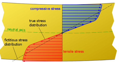
Figure 2 Stress distribution during plastic deformation in an isotropic material [6]
1.1. Testing of brittle materials.
In brittle materials specimens usually break without significant deformation making the determination of flexural yield strength complicated. Therefore, in brittle materials the stress at the onset of fracture represent a more useful parameter. This is often referred to as ultimate flexural strength or bending strength or modulus of rupture.
It is important to note that the bending strength is still determined using the simple beam theory assumptions. However, at fracture the stress distribution within a section will not be linear. Thus, the flexural strength represents a fictitious value that doesn’t correspond to the true state of stress of a material[4-7].
1.2. Four-point bending
Within a beam, coupling of stresses usually occur. In simple beam theory it is known that the relations between Loads p(x), Shear Forces V(x) and Bending Moments M(x) are given by the following relationships:

In brittle materials this substantially influence the result leading to a premature failure. Four-point bending test has the advantage of generating a region subject to a constant bending moment causing shear forces to be null within this length. This allows for a section of the specimen subject to a pure bending moment to be evaluated while testing[4-7].
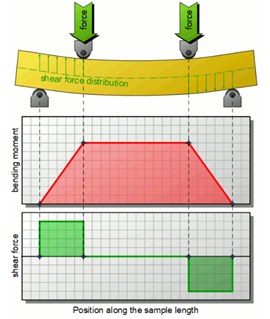
Figure 3: Bending Moment distribution in a beam during three-point bending [6]
According to the ASTM C1121-18 and C1161-18 [8-9], the strength of a beam subject to a four-point bending stress is:

Where P is the applied force at failure, L is the outer (support) length; b is the specimen width and d is the specimen thickness.
2. Design of Experiment
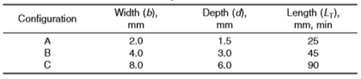
Because of the brittle nature of Ni3Al and other experiments reported in literature [10], during mechanical testing the samples were treated as ceramics. Thus, four-point flexural bending test is performed according to standards ASTMC1161-18 and ASTMC1211-18. Samples and load bearing dimensions are chosen conforming to configuration A of Tables 1 and 4. Moreover, samples are chamfered on their long side.
Table 1 Specimen Size configurations according to standard ASTMC1161-18 and ASTMC1211-18 [8-9]
A load bearing jig conforming to the one of table 4 was manufactured by the SDSU machine shop. Crosshead speed for displacement-controlled testing is chosen according to configuration A of table 2.
Table 2 Crosshead Speed according to standard ASTMC1161-18 and ASTMC1211-18 [8-9]

Samples are loaded until fracture. Assuming a linear elastic beam with a rectangular cross-section, the ASTM standards provide the following formula to calculate ultimate stress:

To account for the chamfer influence on the second moment of inertia, the flexural strength is later multiplied by a correction factor provided in table 3. Thus, the corrected flexural strength S’ is given by:

Table 3 Chamfer Geometry and relative Correction Factor [8-9]
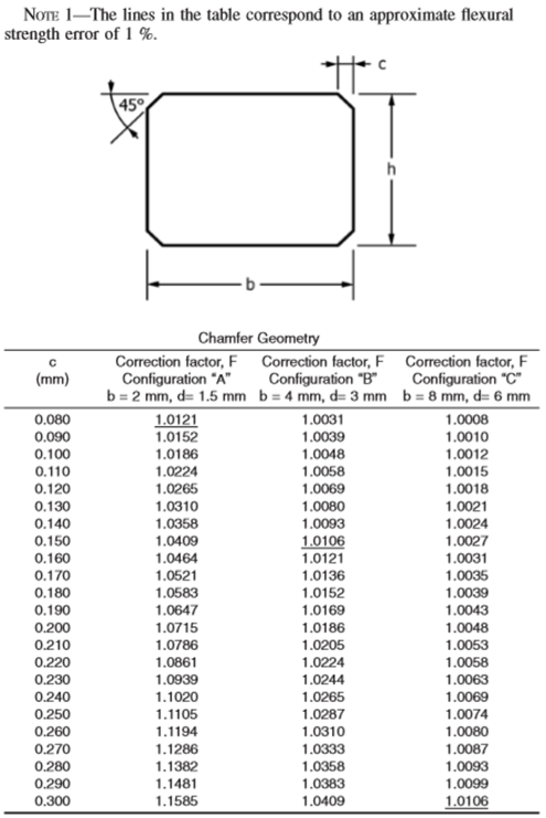
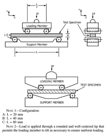
Figure 4 Fixture Span according to standard ASTMC1161-18 and ASTMC1211-18 [8-9]
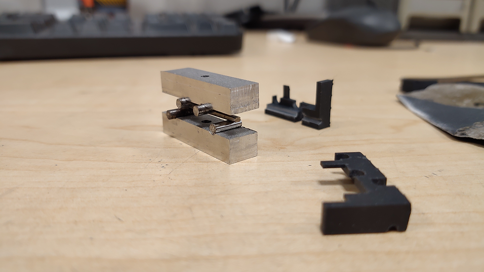
Figure 5 Manufactured loading jig for four-point testing procedure
3. Experimental Procedure
Experiments were conducted using an INSTRON universal testing machine. The Four-point testing loading jig was placed between two compression plates. To ensure a correct load application a 3-D printed sample placer was designed to align to jig at the center of the compression plates. Moreover, the placer was realized to keep all the components of the jig properly aligned with each other before the application of a pre-load. This resulted impossible without the placer due to the very small geometry of the samples and the loading jig. Samples were subject to a steady state crosshead speed until fracture occurred. Figure 6 through 8 show illustrations of the apparatus.
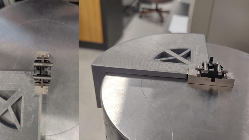
Figure 6 3-D printed Aligner for the bottom loading jig and 3-D printed load bearing placers (in black)
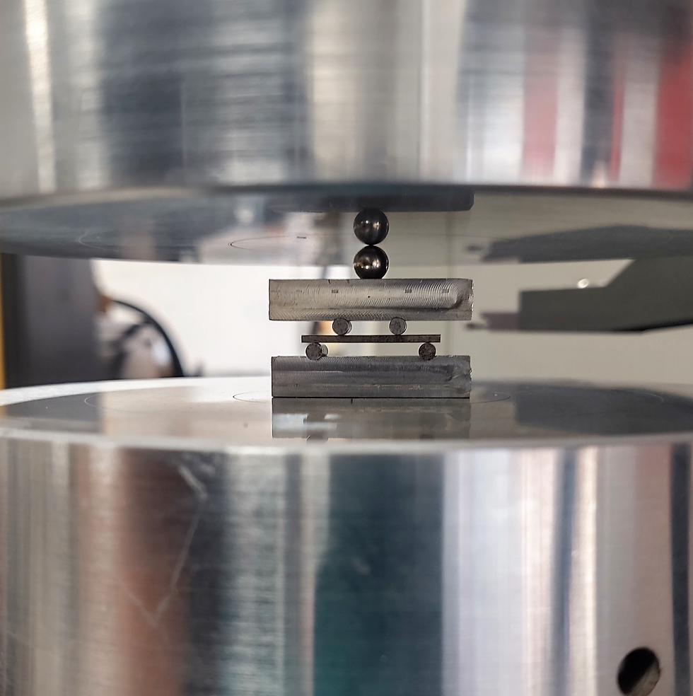
Figure 7 Illustration of the four point testing set up after the application of the preload and the aligner and placers are removed
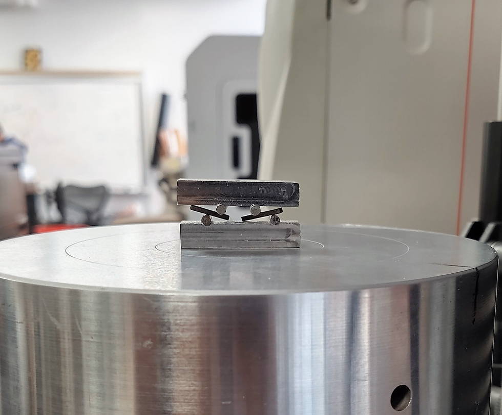
Figure 8 Image taken after test
High Temperature testing
Testing at 300°C and 500°C required the realization of a heating component. This was done by machining a U-shaped piece of rigid Calcium Silicate and by placing a heating band on the inside walls as shown in figure 9. Rigid Calcium Silicate is an incompressible, easy to machine, thermal insulator ceramic. As such, the U-shaped ceramic serves as structural support for the heating bands while also providing thermal insulation through the side walls. To protect the INSTRON machine from the high temperatures involved during testing, two insulating plates made of the same ceramic were fabricated. Moreover, an additional cylindrical component was machined to allow load transfer from the plates to the loading jig while using the heating apparatus. These new components also required the design of a new sample placer that allowed for proper alignment of the pieces prior to the preload application.
A K-type thermocouple was used to evaluate the temperature and placed at a minimal distance from the testing bars. Insulating wool was also used to block airflow from the top of the heating element and minimize convection. The temperature of the heating element was regulated utilizing a variac. The temperature were ramped up and ramped down to allow for minimal thermal stress in the tested material.
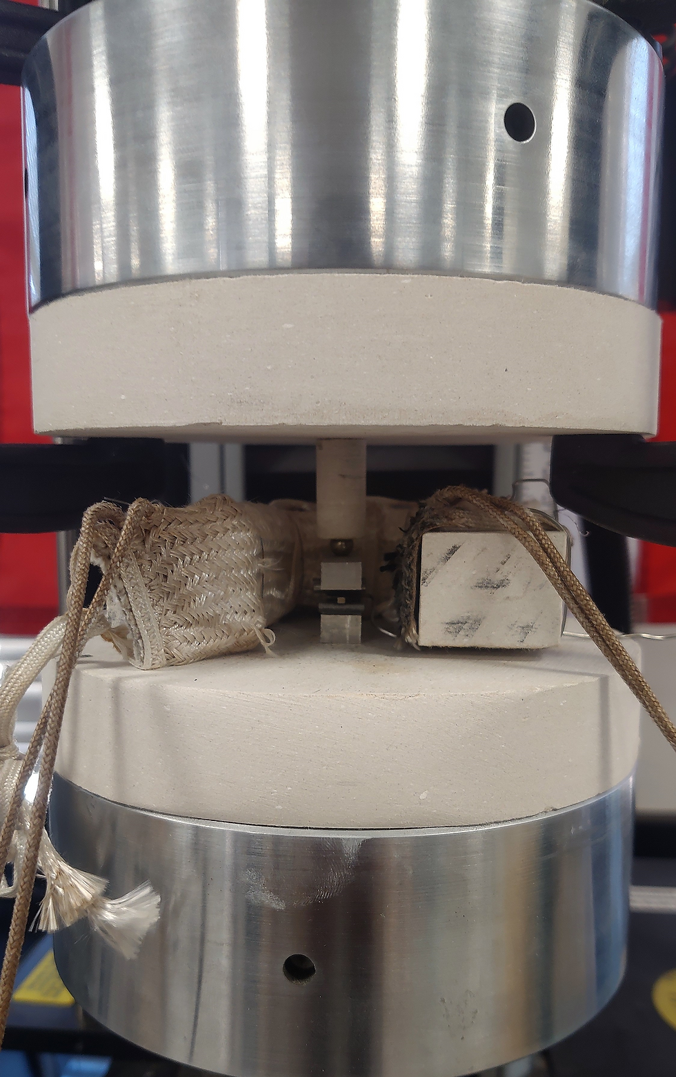
Figure 9 Setup placed in between the protective Calcium Silicate plates and heating bands
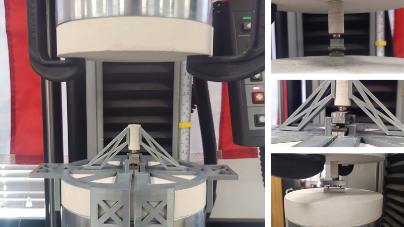
Figure 10 3-D printed Aligner for placement of all the components necessary for high temperature testing
Figure 11 Zoom-in of the setup shows the thermocouple almost touching the sample
Figure 12 Insulating wool is utilized to minimize convection. Thermocouple reading the temperature inside the heating component at 500°C
Results
The results of this test were ground braking. They are currently being analyzed and studied by the author and will be published soon!
References
E. S. C. S. M. Alexander, “Kinetics of Heterogeneous Self-Propagating HighTemperature Reactions,” Intech, vol. i, no. tourism, p. 13, 2012.
A. Feng, O. A. Graeve, and Z. A. Munir, “Modeling solution for electric field-activated combustion synthesis,” Comput. Mater. Sci., vol. 12, no. 2, pp. 137–155, 1998.
J. J. Valencia and P. N. Quested, “Thermophysical Properties, ASM Handbook,” Asm, vol. 15, no. Ref 24, pp. 468–481, 2008.
J. M. Ting, “Flexural strength analysis of brittle materials,” J. Mater. Sci., vol. 38, no. 2, pp. 339–341, 2003.
D. Leguillon, É. Martin, and M. C. Lafarie-Frenot, “Flexural vs. tensile strength in brittle materials,” Comptes Rendus - Mec., vol. 343, no. 4, pp. 275–281, 2015.
Tec-science, “Bending flexural test.” [Online]. Available: https://www.tec-science.com/material-science/material-testing/bending-flexural-test/.
S. Urata, R. Funahashi, T. Mihara, A. Kosuga, and N. Miyasou, “Mechanical properties of materials,” Int. Conf. Thermoelectr. ICT, Proc., pp. 153–156, 2007.
A. International, “Standard Test Method for Flexural Strength of Advanced Ceramics at Elevated Temperatures,” Order A J. Theory Ordered Sets Its Appl., vol. 94, no. Reapproved, pp. 1–17, 1996.
A. International, “Standard Test Method for Flexural Strength of Advanced Ceramics at Ambient,” Order A J. Theory Ordered Sets Its Appl., vol. 94, no. Reapproved, pp. 1–15, 2018.
R. Mitra, Structural Intermetallics and Intermetallic Matrix Composites. 2015.


Commenti